Software
CAD for a First Bracket That Has to Fit
A bracket is a few sketches and the holes that match the hardware. The software should stay out of the way.
- 3 min read
- Software
- Eight more stories
The first useful printed part is usually a bracket: something that holds a sensor, a cable, or a motor where the original tab broke. You do not need a sculpture tool for that. You need parametric CAD, where a hole is a dimension you can change when the screw is M4 and not M3. Browser tools and desktop tools both work if they keep a history. A mesh sculpt does not, and you will redraw the part the moment the measurement was off by a millimeter.
Model the hardware, not the vibe
Start from the face that touches the real object. Place holes at the measured spacing and oversize them a little for the process you print with. Filament holes come out tight. Resin holes come out small if the exposure is hot. Put a flat on the bed side so the bracket does not need a raft of supports under the only face that must be square. Add fillets at inside corners so the layers are not asked to turn on a knife edge.
FreeCAD is enough if you are willing to learn constraints. Fusion and Onshape are enough if you want a quicker first sketch and you accept their account rules. Pick one and make the bracket. Switching tools mid-sketch is how a one-hour part becomes a weekend.
- Name dimensions. Future you will not remember why a hole was 4.4 mm.
- Leave room for a hex nut if you cannot reach the back with a wrench.
- Avoid text on the part until the fit is right. Text is slow forgiveness.
- Print the bracket in the orientation that keeps the screw pull off the layer plane.
Do this next
- 1
Measure the mating part with calipers, including the screw head, not from memory.
- 2
Sketch on the face that mounts, and lock the holes to that face.
- 3
Add thickness before decoration. A rib beats a thicker slab.
- 4
Export millimeters, then check one hole in the slicer with the measure tool.
More from the desk
Eight other notes from the rest of the bench.
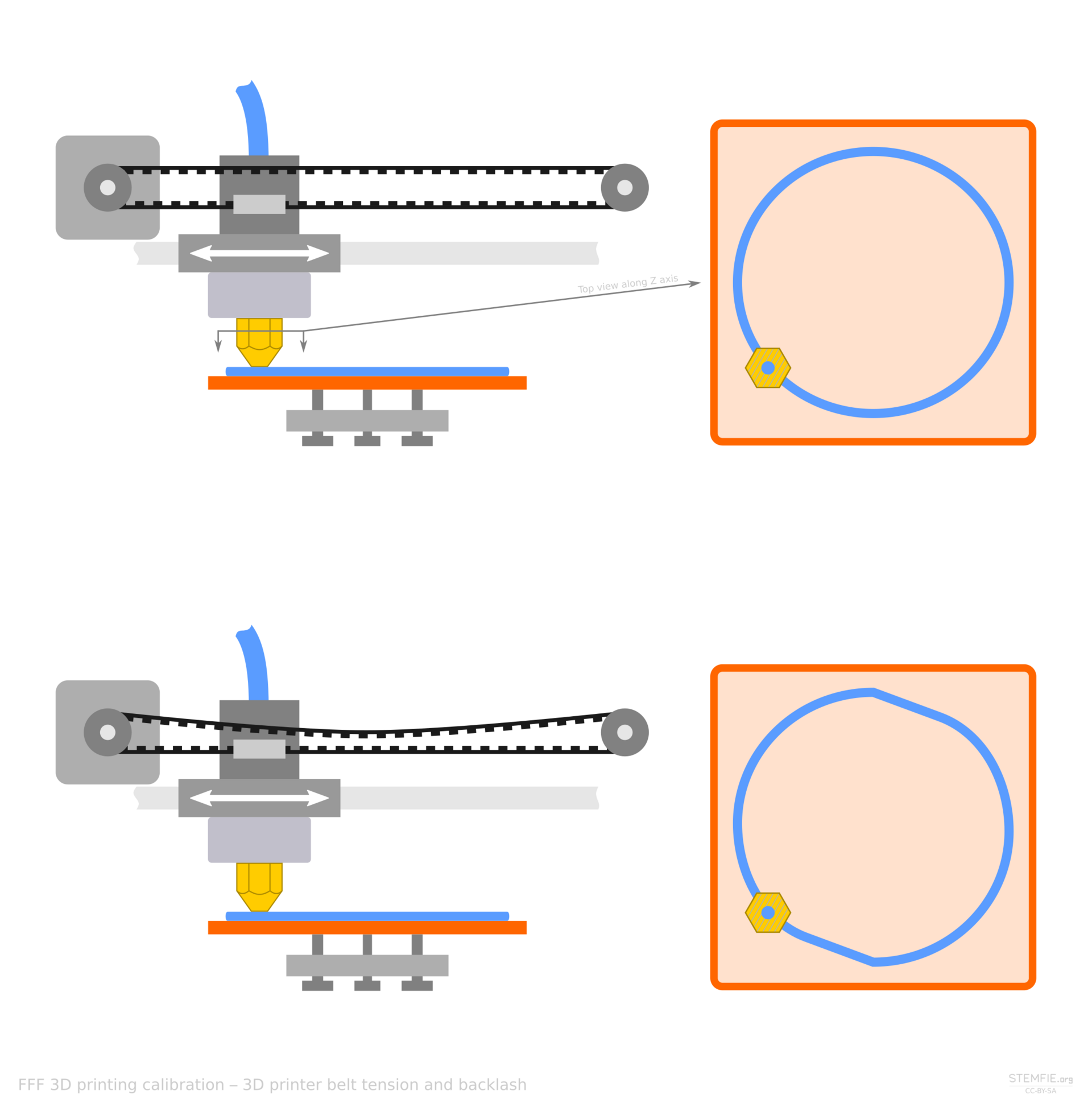 PrintersBelts, Lead Screws, and Linear MotorsMost desks move with belts. Screws trade speed for stiffness. Linear motors remove the belt, and the modest price.
 MaterialsTurning Scrap Plastic Into FilamentA filament extruder can reuse one clean plastic. Mixed scrap, wet flake, and a wandering diameter will not.
 PrintersContinuous Fiber on a Desktop MachineA strand laid into the part is strong along its length. Across the strand, you still have plastic.
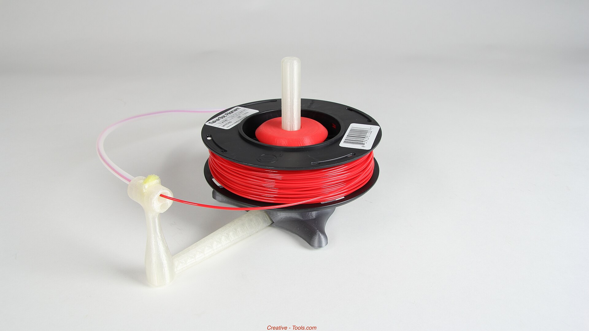 MaterialsFlexible Filament Without the GuessworkFlexible filament buckles when you rush it. Shore hardness and a short path to the nozzle matter more than a secret profile.
 ApplicationsWhat Kitchen Printers Actually DepositA kitchen printer pushes paste through a nozzle. It does not invent a recipe, and it does not clean itself.
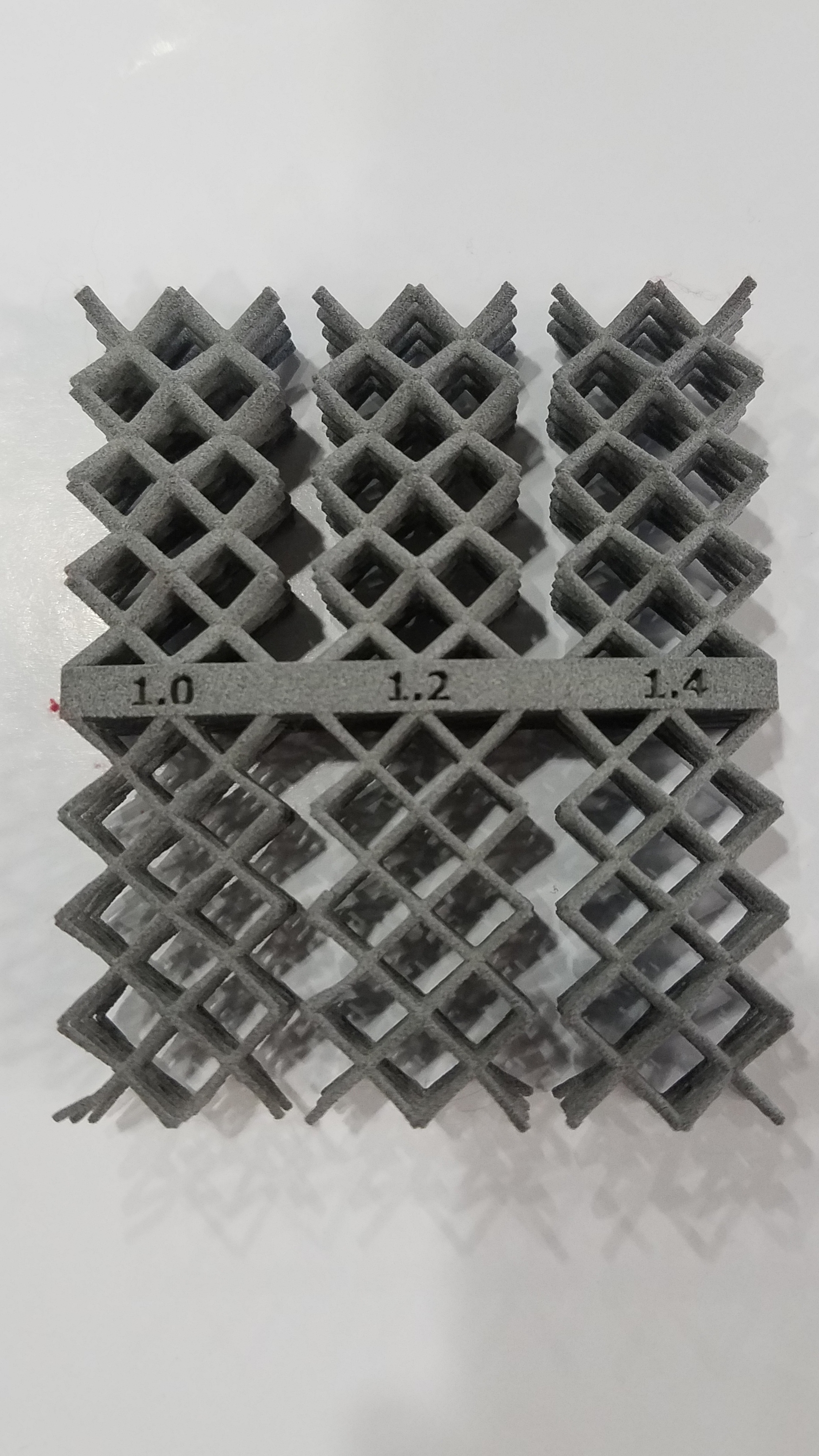 SoftwareFrom a Sentence to a Printable MeshA model generator can hand you a shape in a minute. The slicer still needs a closed, scaled, thick-enough solid.
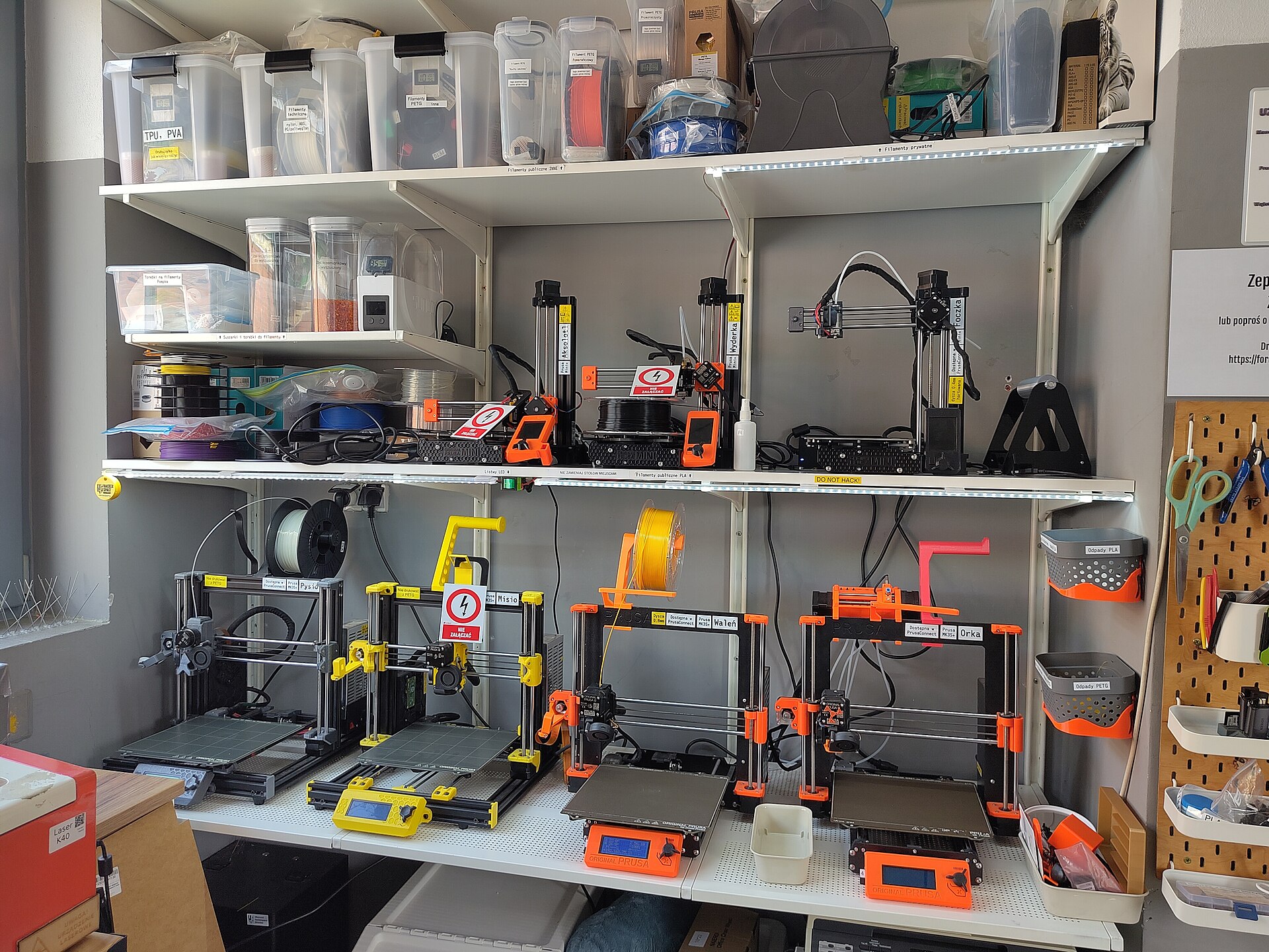 NewsA Desk That Prints, Washes, and Cures ResinThe print is the tidy part. Washing and curing are where a small resin setup usually spills.
 PrintersHow to Compare Resin Printers Without the Spec FogResolution numbers are the loud part. The vat, the film, and the smell decide whether you live with the machine.