
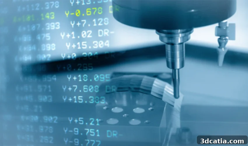
G-Code Explained: The Digital Language Powering Your 3D Printer
The world of additive manufacturing is far more intricate than merely pressing a button and watching a machine create an object. It encompasses a sophisticated sequence of operations, starting from the initial design phase, moving through various preparation stages, and culminating in crucial post-processing steps. Among these pivotal preparatory steps, before any material is extruded or fused, lies the essential process of converting a digital model into machine-readable instructions. This is where slicer software plays an indispensable role. Slicers take a 3D model file, typically an STL or OBJ, and translate it into a control file specifically designed for the 3D printer. This control file is predominantly composed of what is known as G-Code – a powerful, yet often unseen, programming language. G-Code enables the 3D printer to comprehend and execute a precise sequence of commands required to fabricate the final physical part. But what exactly is this digital language, and why is its understanding so critical to the success of the additive manufacturing process?
At its core, G-Code is a numerical control language, originally developed for computer numerical control (CNC) machines, and subsequently adopted and adapted for 3D printing. It consists of a series of alphanumeric commands, primarily categorised as G-commands (for ‘general’ or ‘geometric’ functions) and M-commands (for ‘miscellaneous’ or machine-specific functions). Each command is assigned a specific motion, action, or machine function. The sequential combination of these commands provides the 3D printer with a detailed blueprint of movements, temperatures, extrusion rates, and other critical parameters it must follow to meticulously build the desired part, layer by layer. While G-Code can be manually written, for 3D printing, it is almost exclusively generated automatically by slicing software when it converts your digital design into a printer-ready file. For the purpose of this guide, we will primarily focus on Fused Deposition Modeling (FDM) 3D printers, making references to components like the extruder, print bed (or tray), and thermoplastic filaments particularly relevant. Within this framework, a typical G-Code file will instruct the 3D printer through a precise sequence of movements, material extrusion, heating operations for both the nozzle and bed, and various detection or auxiliary functions. Grasping this fundamental structure is paramount to understanding the profound importance of G-Code; however, let’s now delve into the specific numerical and alphabetical composition of common G-Code commands to better comprehend their individual directives.
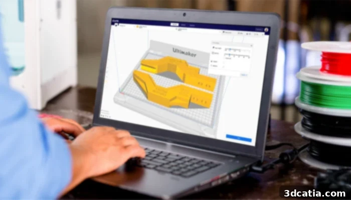
The G-Code language is automatically generated by the slicer (photo credits: Ultimaker Cura)
Understanding the Structure and Components of G-Code
Before dissecting individual commands, it’s crucial to understand the distinction between G-Code and M-Code commands. Both are integral parts of the final control file, instructing the printer on everything from where and how to move to when and how much material to extrude. The primary difference lies in their universality and purpose: G-Codes generally refer to actions or motions (e.g., move in a line, home axes), and these commands are often universally understood across a wide range of CNC machines and 3D printers, adhering to common standards. M-Codes, on the other hand, are ‘miscellaneous’ functions that control specific machine functionalities (e.g., turn on/off fan, set temperature, stop print). These M-Codes can sometimes be more specific to particular printer manufacturers, firmware versions (like Marlin, Klipper, RepRapFirmware), or individual printer lines, though many have become de facto standards. As we observe the examples of G-Code in various contexts, the language is structured using several parameters, each denoted by an alphanumeric value. The fundamental elements required to interpret such code are the specific letter (G, M, X, Y, Z, F, E, S, T) followed by a numerical value, which together define the precise action or state.
The most fundamental parameters in G-Code define spatial positioning and movement. The letters X, Y, and Z directly correspond to the three Cartesian axes of the 3D printer, which establish the coordinates within the build volume. In a standard FDM setup, an increase in the X-value (e.g., X10 from X0) typically moves the printhead to the right, signifying movement along the horizontal axis. An increase in the Y-value moves the printhead backward relative to the front of the machine, representing movement along the depth axis. Similarly, an increase in the Z-value moves the printhead upwards, indicating vertical progression of the layers. These coordinates, often expressed in millimeters, precisely dictate where the extruder should be positioned at any given moment. Beyond positioning, other crucial parameters control the dynamics of the printing process. The letter F denotes the feed rate, which is the speed at which the nozzle moves during a given operation. This value is typically indicated in millimeters per minute (mm/min) and significantly impacts print speed and quality. A higher F-value means faster movement. The letter E, on the other hand, refers to the length of filament to be extruded. This value is also given in millimeters, and it determines how much material is pushed out of the nozzle. The precise control of E-values is essential for consistent extrusion, preventing under-extrusion or over-extrusion. Occasionally, you may encounter lines of text within the G-Code file that begin with a semicolon (;). These are comments, designed to provide human-readable information or explanations about the command that follows, but they are completely ignored by the 3D printer’s firmware. With this foundational understanding of how G-Codes are structured and the meaning of their basic alphanumeric values, let’s now explore some of the most common G-Code and M-Code commands vital for the successful manufacture of a part in 3D printing.
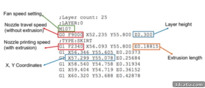
Examples of commands for 3D printing
The G1 command is arguably the most frequently used G-Code, often comprising upwards of 95% of a typical G-Code file. It instructs the 3D printer to perform a linear motion while simultaneously depositing material. This means the extruder moves from its current position to a new specified coordinate (X, Y, Z) at a particular speed (F), and during this movement, it extrudes a calculated amount of filament (E). For example, the command “G1 X10 Y20 F1200 E1.5” would instruct the printer to move its printhead linearly to the X=10mm, Y=20mm position on the print bed, at a speed of 1200 mm/min, while extruding 1.5mm of filament. This command is the workhorse of 3D printing, responsible for building every line and every layer of your model. By contrast, the G0 command operates on the same principle of linear motion, but critically, it does so *without* extruding any material through the nozzle. G0 commands are used for “travel moves,” when the printhead needs to move quickly from one point to another without leaving any filament trail, for instance, between different parts of a layer or when moving from one printed section to begin another. Both G0 and G1 are essential for efficient and precise path planning by the slicer.
The G28 command is a fundamental instruction for initiating any 3D print and is often found at the very beginning of a G-Code file. It commands the 3D printer to “auto home” its axes. This process involves moving the printhead along the X, Y, and Z axes until it makes contact with optical or mechanical end stops located at the extreme edges of the build volume. By doing so, the printer establishes its absolute zero position for all three axes, providing a crucial reference point for all subsequent movements and ensuring accurate placement of the print. If no specific axis is designated (e.g., just “G28”), the machine will home all three axes by default. However, you can also specify individual axes, such as “G28 X” to home only the X-axis, which can be useful for maintenance or during manual calibration. This command is vital for setting up a consistent printing environment and is often followed by other setup commands like bed leveling (e.g., G29) to ensure optimal first layer adhesion and overall print quality.
The G92 command serves a unique and powerful function: it allows you to set or reset the current position of one or more axes, effectively telling the printer “this is now position zero (or any other specified value) for this axis.” While this might seem counter-intuitive after homing, it has several important applications. One of the most common uses for G92 is to reset the extruder’s position, typically with “G92 E0”. This command tells the printer to consider the current amount of extruded filament as zero, regardless of how much has actually been pushed out. This is often done at the beginning of a print or after a retraction sequence to ensure that subsequent extrusion commands are relative to a known starting point, crucial for maintaining consistent filament flow. G92 can also be used to create offsets or define new temporary origins for specific print scenarios, offering advanced users a way to fine-tune coordinate systems for complex projects or multi-part printing configurations.
Temperature control is paramount in FDM 3D printing, dictating how well plastic melts, flows, and adheres. The M104 and M109 commands are dedicated to managing the extruder (nozzle) temperature. The M104 command, with syntax like “M104 S200 T0”, instructs the printer to begin heating the designated extruder (T0 in the case of a dual-extrusion system, where T1 would be the second extruder) to a target temperature, indicated by the ‘S’ parameter (e.g., S200 for 200 degrees Celsius). This command is “non-blocking,” meaning the printer will initiate the heating process but immediately proceed to the next G-Code command in the file without waiting for the target temperature to be reached. This allows for parallel operations, such as pre-heating the nozzle while the bed is still heating or while the axes are homing, optimizing the start-up sequence. In contrast, the M109 command, with similar syntax, is “blocking.” It also sets the extruder temperature, but critically, the printer will *pause* its execution and wait until the extruder has fully reached and stabilized at the specified temperature before continuing with any subsequent commands. This ensures that the material is at the ideal viscosity for proper extrusion from the very first line of filament, preventing issues like poor adhesion or under-extrusion at the print’s outset.
In a parallel fashion to extruder temperature control, the M140 and M190 commands are used to manage the temperature of the heated print bed. A stable and appropriately heated print bed is vital for good first-layer adhesion, preventing warping (especially with materials like ABS), and ensuring the overall stability of the printed part. The M140 command, typically written as “M140 S60”, instructs the printer to begin heating the print bed to the specified temperature (e.g., S60 for 60 degrees Celsius). Like M104, this command is “non-blocking,” allowing the printer to continue processing other commands while the bed warms up. This is particularly useful as print beds often take longer to reach their target temperature compared to extruders. Correspondingly, the M190 command is the “blocking” version for the heated bed. A command like “M190 S60” will not only initiate heating of the print bed to 60 degrees Celsius but will also compel the printer to wait until that temperature is attained and stable before moving on to the next instruction in the G-Code file. This ensures that when the first layer of filament is deposited, it encounters an adequately heated surface, maximizing adhesion and significantly reducing the risk of print failure. Together, M104, M109, M140, and M190 provide comprehensive thermal control over the FDM 3D printing process, critical for successful outcomes with a wide range of thermoplastic filaments.
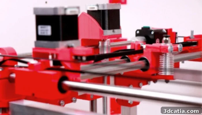
FDM 3D printers have 3 axes (X, Y, Z) that allow them to be positioned in the printing coordinates
Final Recommendations and the Power of G-Code Knowledge
The array of G-Codes and M-Codes available for 3D printers is indeed vast, extending to well over a thousand distinct commands that dictate every conceivable action and state of the machine. This extensive language governs everything from intricate movements and precise material extrusion to fan speeds, motor disablement, and error reporting. It is precisely because of this complexity that slicing software has become indispensable, automatically generating this elaborate code prior to the actual manufacturing process. For the majority of users, relying on the slicer is sufficient, as it expertly translates user-friendly settings into the intricate G-Code necessary for a successful print. However, understanding the fundamentals of these codes can prove incredibly useful and insightful, particularly for those looking to delve deeper into the mechanics of 3D printing.
For advanced users, a basic comprehension of G-Code can be an invaluable asset for several reasons. It empowers you to: 1) **Troubleshoot print issues:** By examining the G-Code, you can often pinpoint why a print failed, whether it was an incorrect temperature command, an illogical movement path, or an improper extrusion rate. 2) **Optimize print settings:** Manual adjustments to G-Code can unlock fine-tuning capabilities beyond what a slicer’s GUI offers, allowing for precise control over retraction settings, acceleration, jerk, and other parameters that dramatically impact print quality and speed for specific materials or geometries. 3) **Customize start and end G-Code:** Tailoring the initial and final sequences of your print can automate pre-print routines (like nozzle priming or bed leveling) and post-print actions (like parking the printhead or cooling down), improving workflow efficiency and print reliability. While direct manual editing of an entire G-Code file is highly complex and generally not recommended for beginners – as incorrect commands can potentially damage your 3D printer – understanding snippets and common commands allows for targeted, impactful modifications. It is always wise to back up your G-Code files before making any manual edits and to test changes cautiously. We strongly encourage enthusiasts and professionals alike to continue exploring and learning about how these advanced solutions work, familiarizing themselves with the various commands available, and appreciating the intricate digital system that underpins the magic of additive manufacturing. This deeper understanding will not only enhance your printing capabilities but also transform you into a more proficient and confident 3D printer operator.
What are your thoughts on the significance and practical applications of G-Codes in 3D Printing? We invite you to share your insights in a comment below or engage with us on our Facebook and Twitter pages. And don’t miss out on the latest advancements and news in the additive manufacturing world – be sure to sign up for our free weekly newsletter, delivered straight to your inbox!