
Mastering 3D Print Quality: A Comprehensive Guide to Preventing and Fixing Elephant’s Foot
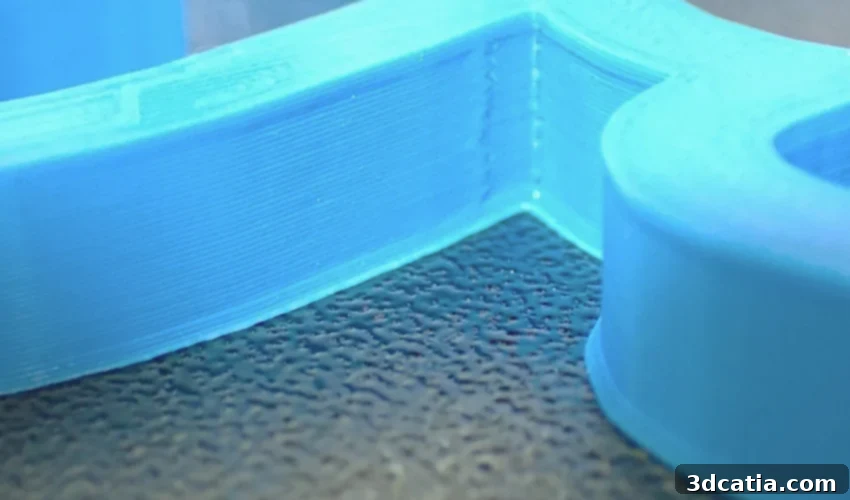
Additive manufacturing, particularly Fused Deposition Modeling (FDM), offers unparalleled design freedom and the ability to rapidly prototype complex geometries. However, unlocking this potential relies heavily on precise printer configuration and an optimized design and modeling workflow. Neglecting these crucial steps can lead to a host of common 3D printing issues, ranging from stringing and warping to ghosting. Among these, a particularly prevalent and frustrating problem, especially in FDM 3D printing, is known as the “elephant’s foot.” This phenomenon manifests when the initial layer of a print expands horizontally, extending wider than the intended design and creating a distinct, flared base that visually resembles the broad foot of an elephant. This guide will provide a comprehensive overview of elephant’s foot, exploring its underlying causes and offering practical, actionable solutions to prevent and rectify it, ensuring superior print quality and dimensional accuracy.
The primary cause of the elephant’s foot effect is the combination of the printing nozzle’s close proximity to the build plate and the pressure it exerts on the freshly extruded, still-soft filament. During the printing process, if the nozzle is set too low (often referred to as an incorrect “Z-offset”), it pushes down on the first layer as it’s laid down. This compression causes the molten plastic to spread outwards, beyond its designed perimeter. Furthermore, the heat from the print bed, while essential for adhesion, can keep the initial layers in a semi-molten state for longer, making them more susceptible to this outward spread due due to gravity and the nozzle’s pressure. This “z-stepping” effect, where the nozzle is effectively squashing the first layer, significantly diminishes the overall dimensional accuracy and manufacturing tolerances of the final part. This often leads to significant challenges, or even impossibilities, during part assembly as components may not fit together precisely. Beyond functional implications, the visual appearance of the part is also compromised by this error, presenting an undesirable aesthetic flaw. While post-treatment can offer some improvement, the elephant’s foot frequently remains noticeable, impacting the professional finish of the printed object. Understanding these root causes is the first step toward achieving flawless 3D prints.
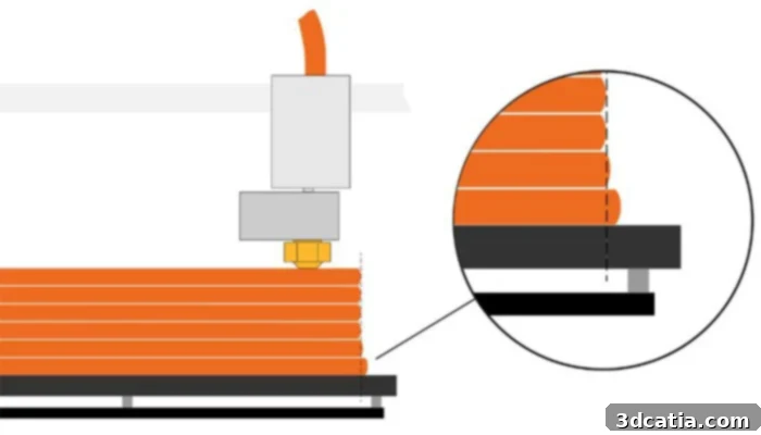
Photo credits: Prusa
Essential Strategies to Avoid Elephant’s Foot in 3D Printing
Addressing the elephant’s foot requires a multi-faceted approach, starting with fundamental printer setup and extending into sophisticated software adjustments. The most critical initial step involves ensuring the build plate is perfectly level and maintaining the correct Z-offset – the precise distance between the nozzle and the print surface for the first layer. Manual calibration is a time-tested method to achieve this precision. To calibrate your Z-offset, you will need a standard sheet of paper (typically 0.1mm thick) or a feeler gauge of a known thickness. Begin by manually moving the nozzle to several points across the print bed. At each point, slide the paper or feeler gauge between the nozzle and the print bed. Adjust the Z-height until you feel a slight resistance when moving the paper back and forth – it should drag a little but not be gripped tightly. This indicates the optimal gap for the first layer. Once the Z-offset is set, it’s highly recommended to conduct a single-layer test print, such as a calibration square or a large disk, to verify the accuracy of your settings. This test print will quickly reveal any underlying issues before you commit to a full print.
The results of your test print will clearly indicate whether further recalibration is needed. You will typically encounter one of three scenarios. If the nozzle is too high, the extruded filament will not adhere properly to the build plate, appearing as disconnected lines or “voids” where the plastic has lifted or not stuck. Conversely, if the nozzle is too low, it will scrape against the build plate, creating visibly thin, squashed lines with distinct “grooves” or even causing the nozzle to drag and block extrusion. In both these cases, the Z-offset requires immediate adjustment and another test print. A successful alignment, however, will produce a smooth, consistent, and well-adhered first layer, characterized by solid, uniform lines that seamlessly merge without gaps or excessive squishing. This ideal first layer is crucial for the foundation of your print and sets the stage for high-quality results, as perfectly depicted in the image below, illustrating the critical balance required for optimal nozzle-to-bed distance.
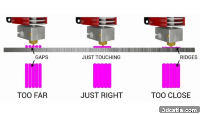
Maintaining the correct distance between the nozzle and the printing plate is key to preventing elephant’s foot.
Beyond mechanical calibration, temperature control plays a vital role in preventing the elephant’s foot effect. It is essential to ensure that both the extruder (nozzle) and the heated build plate temperatures align precisely with the filament manufacturer’s recommendations. If the print bed is too hot, the initial layers will remain molten for too long, making them prone to spreading under the weight of subsequent layers and the nozzle’s pressure. Conversely, if the bed temperature is too low, the filament may not adhere properly, leading to warping or detachment. Similarly, an extruder temperature that is too high can result in overly fluid plastic that spreads excessively upon extrusion, while a temperature that is too low can cause under-extrusion and poor layer adhesion. Finding this ideal temperature balance is critical. If, after meticulously following these calibration and temperature guidelines, the desired results are not achieved, you can explore indirect solutions through slicer software settings and adhesion aids.
One highly recommended indirect approach is the implementation of a “raft” during the printing process. Rafting involves printing several sacrificial layers of material directly onto the build plate before the actual part fabrication commences. This creates a stable, larger base on which the final object will be printed. The presence of this raft acts as a buffer between the first layer of your model and the printing plate, effectively absorbing any potential elephant’s foot deformation. The defect will form on the raft itself, which is subsequently removed during post-processing, leaving the actual part’s base perfectly crisp and dimensionally accurate. While rafts consume more material and add to print time and post-processing, they are invaluable for parts with small contact areas, intricate first layers, or when working with materials notoriously difficult to adhere to the build plate. This method offers a robust solution for ensuring the bottom of your print maintains its intended geometry, significantly reducing the impact of the elephant’s foot on your final product.
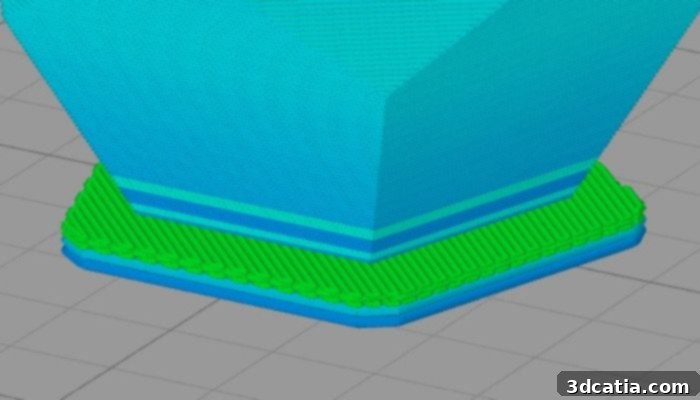
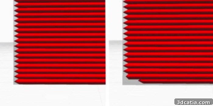
When utilizing a raft, the elephant’s foot forms on the sacrificial raft layer, not on the model itself (Photo credit: Simplify3D).
Achieving Improved Results Through 3D Modeling and Slicer Software
Beyond printer calibration, significant improvements in combating the elephant’s foot can be made during the 3D modeling and slicing phases. One effective manual technique is to apply a slight 45° chamfer or bevel to the bottom edge of your 3D model. This subtle modification creates a tiny angled space at the base of the part. When the first layer inevitably expands due to nozzle pressure and heat, this chamfer provides a relief area, causing the squish to occur within the chamfered region rather than extending beyond the intended part boundary. This clever trick effectively “hides” the elephant’s foot, making the base appear sharp and dimensionally accurate. Implementing this in your CAD software, even a chamfer as small as 0.1-0.2mm, can make a noticeable difference in the final print quality, especially for parts requiring precise fits.
Modern slicer software also offers sophisticated tools specifically designed to counteract the elephant’s foot effect automatically. For instance, PrusaSlicer, a popular and robust slicing software, includes an “Elephant’s Foot Compensation” parameter, typically found in its advanced and expert modes. This setting allows users to specify a negative offset (e.g., -0.1mm to -0.3mm) that the software applies to the initial layer’s perimeter. The principle is straightforward: the first layer is modeled and printed slightly narrower than the subsequent layers, pre-compensating for the expected horizontal expansion. This ensures that when the first layer squishes outwards, it precisely matches the dimensions of the layers above it. Although the 3D model preview within the slicer might appear distorted at the base due to this compensation, the final physical print will exhibit the intended dimensions and a perfectly straight edge, effectively eliminating the elephant’s foot without compromising the overall appearance or functionality of the part.
Another widely used and versatile tool for adjusting design parameters is Cura. Within Cura, you can utilize the “Horizontal Expansion” setting to finely tune the dimensions along the X and Y axes of your model. This parameter is incredibly versatile: a positive value is typically used to counteract material shrinkage, which is a common characteristic of plastics like ABS or nylon, helping to ensure parts print at their desired size. However, to specifically address the issue of a flattened and wider first layer caused by the elephant’s foot, a negative value should be applied to this setting. By applying a negative horizontal expansion, Cura effectively shrinks the perimeter of the initial layer (or initial few layers) by the specified amount. This pre-correction means that when the first layer inevitably expands outwards due to nozzle pressure and heat, it will expand to the intended dimensions rather than exceeding them. The underlying principle of this method is quite similar to PrusaSlicer’s compensation feature, giving you the flexibility to choose the solution that best integrates with your preferred 3D printing software and workflow.
In Cura, setting a negative horizontal expansion value can effectively counteract printing errors like the elephant’s foot (Photo credits: Cura).
Finally, while prevention is always the best strategy, the elephant’s foot effect can also be addressed during post-processing. It’s important to note that while slicer solutions like horizontal expansion effectively reduce crushing along the X and Y axes, significant vertical distortion (along the Z-axis, if the initial layer is excessively compressed) might remain, although this is less common for elephant’s foot specifically. If you find yourself with a part exhibiting a noticeable elephant’s foot despite your best efforts, or if dealing with intricate Z-axis compensations seems challenging, you can rectify the manufacturing defect after the print is complete. One highly effective and straightforward method is to use a deburring tool. This specialized tool, often with a swiveling blade, allows for precise and careful removal of the excess material flared out at the base of the part. By gently scraping along the bottom edge, you can trim away the expanded plastic, restoring the part’s intended profile. Deburring tools are widely available and relatively inexpensive, with prices typically ranging between 10 and 30 dollars depending on the supplier and quality. For a smoother finish, especially on more visible parts, you can follow up deburring with fine-grit sanding or filing. While post-processing is a reactive solution and can be time-consuming, it offers a valuable last resort for salvaging parts and achieving an acceptable finish.
In summary, the elephant’s foot in 3D printing is a common but entirely preventable issue that can significantly compromise the dimensional accuracy, functional fit, and aesthetic appeal of your printed parts. By understanding its causes—primarily improper Z-offset, suboptimal bed temperatures, and initial layer squish—you are now equipped with a comprehensive arsenal of strategies to combat it. From meticulous bed leveling and Z-offset calibration to optimizing extruder and bed temperatures, and leveraging advanced slicer settings like “Elephant’s Foot Compensation” or “Horizontal Expansion,” a perfect first layer is within reach. Additionally, employing adhesion aids like rafts or even applying a subtle chamfer in your 3D model can proactively mitigate the problem. And for those instances where prevention wasn’t entirely successful, post-processing techniques such as deburring offer a viable means of rectification. Embracing these techniques will empower you to consistently produce high-quality, dimensionally accurate 3D prints, saving both time and material in the long run.
Have you ever encountered the “elephant foot” effect when working with 3D printing, or do you have any additional tips to share? We’d love to hear your experiences! Let us know in a comment below or connect with us on ourLinkedIn,Facebook, andTwitter pages! Don’t forget to sign up for our free weeklyNewsletter here, bringing the latest 3D printing news straight to your inbox! You can also find all our insightful videos on ourYouTube channel.