

Optimizing FDM 3D Printing: A Comprehensive Guide to Retraction and Printhead Movement Settings
Additive manufacturing, particularly Fused Deposition Modeling (FDM) 3D printing, has revolutionized prototyping and production across countless industries. However, achieving high-quality, flawless prints often goes beyond just a great design. A critical phase in the 3D printing workflow involves meticulous configuration and adjustment of printing parameters within a slicing software. This crucial step ensures that your chosen design translates into a physical object precisely as intended, minimizing common printing errors and maximizing print quality. Popular slicing solutions on the market, such as Cura and PrusaSlicer, offer a vast array of settings to fine-tune every aspect of the printing process. Among the most vital settings for FDM 3D printing are those governing the movement of the printhead in the build zone, especially during non-printing travel moves. Understanding and mastering these movements, particularly the role of retraction, is paramount for producing professional-grade 3D prints.
What Is Retraction in 3D Printing?
To truly understand optimal printhead movement, we must first delve into the concept of retraction. Retraction is a sophisticated mechanism employed by 3D printers designed to prevent unwanted material extrusion during travel moves. Essentially, when the printhead needs to move from one printed section of an object to another without laying down material, the extruder motor momentarily pulls the filament back (retracts it) into the nozzle. This action rapidly reduces the pressure inside the nozzle, preventing molten plastic from oozing out and creating unsightly defects on your print. Without proper retraction, the hot, viscous material may remain suspended at the nozzle tip, forming thin strands (known as “stringing”) or depositing small blobs of plastic across non-printed areas as the printhead travels. By actively pulling the filament back, retraction ensures that material flow is precisely controlled, ceasing when movement begins and restarting only when deposition is required again.
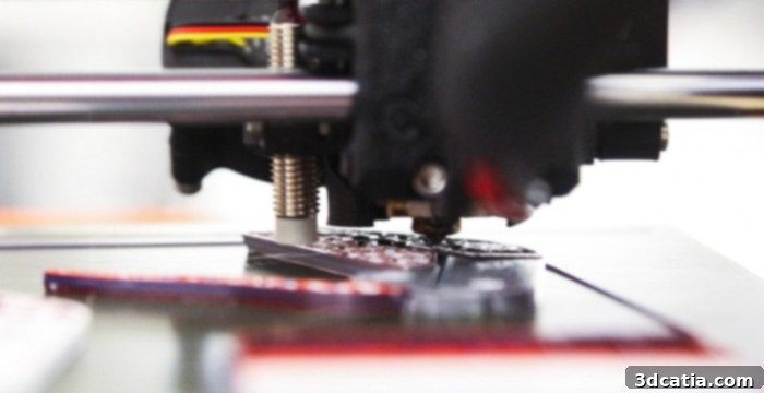
The extruder is capable of retracting a portion of filament to prevent it from flowing between printhead movements.
The effectiveness of retraction largely depends on several configurable parameters, which must be tailored according to the specific material being used and the type of extrusion system present on your 3D printer. A key distinction lies between Bowden and direct drive extruder systems. In a Bowden setup, the extruder motor is mounted on the printer frame, pushing the filament through a long PTFE tube (the Bowden tube) to the hotend. This distance means that retraction movements need to be longer to compensate for the slack and friction within the tube. While Bowden systems often allow for faster printhead movements due to lighter gantry weight, they typically require greater retraction distances and potentially higher retraction speeds. Conversely, direct drive extruders have the motor mounted directly on the printhead, right above the hotend. This close proximity means the filament path is much shorter and more direct, leading to superior and more precise retraction. With direct drive systems, much shorter retraction distances and lower speeds are usually sufficient, often yielding cleaner results and better control over flexible filaments.
When working with flexible materials such as TPU or TPE, retraction becomes even more nuanced. Due to their elastic nature, these filaments can stretch and compress, making precise retraction challenging. Often, it’s recommended to reduce retraction distances and speeds significantly, or even disable retraction entirely for extremely soft flexibles, to avoid grinding the filament, creating clogs, or losing control over the material flow. Instead, compensatory settings like “wipe” or “coast” might be preferred. Users must also carefully consider the retraction speed. If the speed is set too high, the filament can be damaged, stretched, or even chewed by the extruder gears, rendering it unusable or causing clogs. However, high speeds are effective at minimizing fluid leakage. Conversely, if retraction speed is too low, the molten plastic may still have time to ooze out before the pressure fully drops, increasing the likelihood of stringing. The ideal speed strikes a balance: fast enough to prevent oozing, but slow enough to protect the filament and ensure smooth operation. Proper retraction calibration is key to avoiding common print defects like stringing – those fine threads of plastic that web between printed parts – thereby significantly enhancing the aesthetic quality and dimensional accuracy of your final product.

Stringing in 3D printing (photo credits: 3Dnatives)
Beyond the fundamental distance and speed, slicers offer more granular control with advanced retraction settings. Two particularly useful settings are the “retraction extra prime amount” and “retraction minimum travel.” The retraction extra prime amount, sometimes called “extra restart distance,” is a small additional amount of material that is extruded immediately after retraction before printing resumes. This compensates for any material that might have been lost or pulled back slightly too far during the travel move, ensuring that extrusion starts precisely and consistently without underextrusion or gaps. This setting is particularly interesting for flexible filaments, which often require additional pressure to flow smoothly and consistently from the nozzle. The “retraction minimum travel” setting dictates the minimum distance the printhead must travel before a retraction is initiated. If a travel move is shorter than this specified distance, the slicer will skip retraction, deeming the time saved by not retracting to be more beneficial than the minimal oozing that might occur over such a short distance. While setting this value too high can lead to visible stringing on short movements, setting it too low can result in an excessive number of retractions, increasing print time and potentially causing wear on the extruder gears or heat creep if the hotend isn’t designed for such rapid thermal cycling. Fine-tuning these parameters is crucial for achieving an optimal balance between print speed, material integrity, and surface finish.
Types of Displacements in FDM 3D Printing
Beyond retraction, the overall strategy for printhead displacement during non-printing moves plays a critical role in print quality and efficiency. Slicers offer various modes to manage these movements, each with its own advantages and disadvantages. These displacement types need to be carefully adjusted and configured based on the specific design of the part and the desired outcome for the 3D print. We’ve outlined three essential types of displacement modes to consider:
Combing Mode
Combing mode is a clever setting that intelligently dictates how the printhead moves between different printed areas of a part, aiming to reduce the necessity for retraction. When combing is enabled, the slicer attempts to keep the nozzle within the confines of the already printed or future printed areas of the model during travel moves. Instead of retracting and taking the shortest path across open air, the printhead “combs” over the part, allowing any small oozes of filament to deposit in less visible areas, such as infill or inside walls, where they are less likely to affect the aesthetic quality of the outer surfaces. This strategy significantly reduces the number of retractions, which in turn can lead to faster print times and less wear on the extruder. Of course, there are situations where it is impossible to move the 3D printhead to the start point of the next layer without crossing an open area, in which case some retraction will still be required. However, by enabling this mode, the slicer will automatically choose not to retract whenever a “safe” path within the model’s perimeter is available.
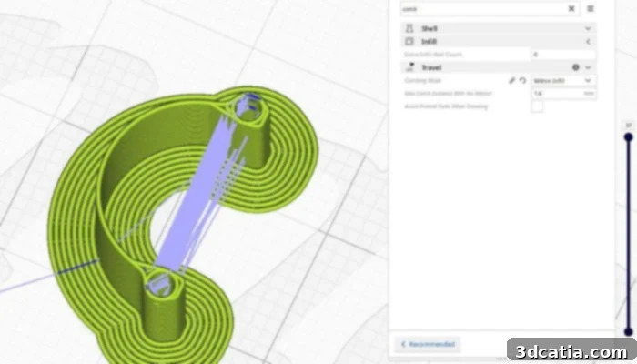
Photo Credits: UltiMaker
Combing mode typically offers several sub-options, each influencing print quality and print time differently. In most slicer software, these options vary in name but serve similar functions:
- “All” (or “No Retraction within Infill”): In this mode, the 3D printer head will comb over any part of the printed model, including infill and internal perimeters. This results in the fewest retractions and potentially longer travel paths within the model, leading to slightly longer printing times but a very clean exterior surface.
- “Off” (or “No Combing”): This option largely prevents the movement of the 3D printer head over already printed parts of the model. Retraction will occur for almost every travel move, regardless of distance, which minimizes surface artifacts but might increase print time and retraction-related issues.
- “Within Infill”: This mode directs the printhead to comb only over the infill areas of the part. The head will not travel over the top and bottom layers or outer perimeters, thereby preserving their surface quality. This is particularly useful for parts where a smooth exterior is paramount, but some minor artifacts within the infill are acceptable.
- “Not in Skin” (or “Outer Walls Only”): This advanced setting ensures that the nozzle never combs over the outer layers or “skin” of the model. It’s ideal for models that demand a perfectly smooth top surface where any threading or marks on the outer walls would be highly visible. This mode will allow combing within the inner perimeters and infill, but prioritize clean external surfaces, even if it means performing more retractions.
If you are using a dual extrusion printer, such as for multi-material or multi-color prints, it is often recommended to use the “Within Infill” option. This prevents contamination of inks or materials on the first and last visible layers by keeping unwanted oozing confined to the internal structure. When dealing with flexible materials, the “All” option is generally preferred. By reducing the overall number of retractions, it minimizes the risk of the material tearing, tangling, or grinding in the extruder, thereby ensuring better print quality and reliability with challenging filaments.
Avoid Printed Parts While Traveling
The “Avoid Printed Parts While Traveling” setting is a powerful tool to further enhance surface quality and prevent nozzle-to-print collisions. When activated, the slicer intelligently calculates a path for the printhead that navigates around already printed parts rather than directly passing over them. This creates a safer travel route, minimizing the risk of the nozzle dragging across the delicate top surfaces of your print, which can lead to unsightly surface defects, scratches, or unwanted material mixing (especially with multi-color prints). This option can only be effectively utilized if you have previously enabled some form of Combing Mode, as it builds upon the slicer’s ability to plan non-extruding travel paths. In essence, it tells the printhead, “If you have to move over the print, try to stay within its boundaries (combing), but if you can avoid touching any existing part altogether, please do.”
The combined use of Combing Mode and “Avoid Printed Parts While Traveling” can dramatically improve overall print quality and reduce the occurrence of various problems on the surface of your parts. By preventing accidental nozzle contact, these settings mitigate potential defects such as warping caused by physical disturbance, reduced stringing as the nozzle travels clear of the model, and deformation of delicate features. It ensures a smoother, more consistent finish, which is particularly critical for aesthetic parts or those with tight tolerances.
Z-Hopping
Z-Hopping, also known as “Z-Lift” or “Lift Z,” is another crucial technique used in conjunction with retraction to prevent the nozzle from dragging across the print surface during non-printing moves. This technique involves the printhead briefly lifting (hopping) along the Z-axis by a small, configurable amount immediately before a travel move and then lowering back down to the print plane once it reaches its destination. This vertical lift creates a crucial gap between the nozzle tip and the printed part, effectively eliminating any potential contact during travel. By enabling different types of Z-hopping, users can achieve much cleaner and more accurate prints, free from scuffs, blobs, or stringing that results from nozzle drag.
The benefits of Z-hopping are numerous. Firstly, it prevents the hot nozzle from scratching or marring the top surface of an already printed layer, preserving its smooth finish. Secondly, it drastically reduces the chances of the nozzle knocking over delicate features or tall, thin structures, improving overall print reliability, especially with complex geometries. Thirdly, it provides an additional safeguard against oozing and stringing. Even if a tiny amount of filament manages to escape after retraction, the raised nozzle ensures this material won’t make contact with the printed part during travel, thus keeping the print clean. There are several scenarios and types of Z-jumps that can be activated:
- Z-Jump During Retraction: This is the most common implementation, where the Z-axis lifts simultaneously with the filament retraction.
- Z-Jump During Layer Change: Some slicers offer the option to lift the nozzle when the printer moves to start a new layer. This reduces the possibility of damage to the printed layer, especially when moving between different parts of a multi-part print or during the initial moments of a new layer’s deposition.
- Z-Jump After Purge Tower (for multi-extrusion): In multi-material or multi-color printing, a purge tower is often used to ensure color/material consistency. A Z-jump after purging creates a gap between the purge tower and the part, preventing any residual material from the nozzle from contaminating the part during travel moves to the object.
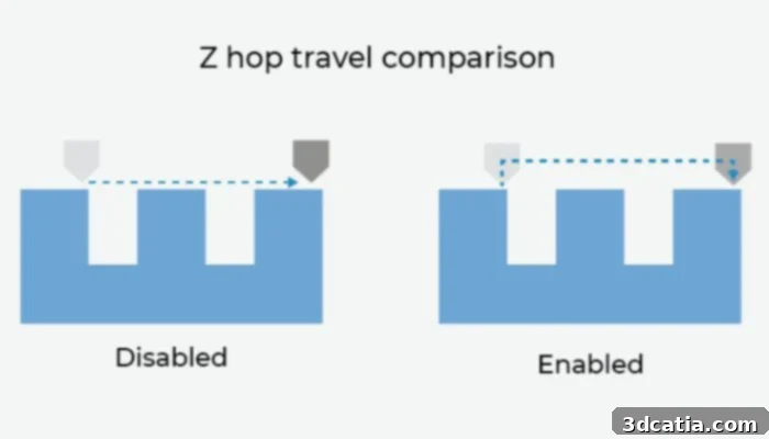
Photo Credits: BCN3D
Mastering retraction and printhead displacement settings is not just about avoiding defects; it’s about unlocking the full potential of your FDM 3D printer. By understanding how these mechanisms work and how their various parameters interact, you can dramatically improve print quality, reduce material waste, and achieve consistent, professional results. Experimentation and calibration are key to finding the perfect balance for your specific printer, filament, and print geometries. Have you had issues with prints due to retraction or printhead movements? Let us know in a comment below or on our LinkedIn, Facebook, and Twitter pages! Don’t forget to sign up for our free weekly Newsletter here, the latest 3D printing news straight to your inbox! You can also find all our videos on our YouTube channel.