
FDM 3D Printing Troubleshooting: Your Ultimate Guide to Solving Common Problems and Achieving Flawless Prints
3D printing, particularly with its Fused Deposition Modeling (FDM) technology, has revolutionized design and manufacturing, opening up unprecedented possibilities for creators and innovators. From rapid prototyping to complex functional parts, the versatility is immense. However, unlocking this full potential hinges on consistent, reliable print quality. While the technology is powerful, users frequently encounter various challenges that can hinder successful prints, sometimes even with the simplest models. These issues can be frustrating, leading to failed prints, wasted material, and lost time. But why do these problems occur? What are their root causes, and, more importantly, how can they be effectively resolved? This comprehensive guide delves into the most common defects and errors encountered in filament-based FDM 3D printing, providing actionable solutions. While other 3D printing processes and materials have their unique sets of challenges, our focus here is exclusively on FDM, addressing the primary hurdles that users typically face. Understanding these issues and their fixes is key to transforming frustrating failures into successful, high-quality 3D prints.
Addressing Adhesion Challenges on the Build Plate
The success of any FDM 3D print begins with its foundation: the initial layers. These layers are critical as they establish the base of your model and must adhere firmly to the printing surface. Poor first-layer adhesion is a pervasive problem that can manifest in various print defects. To ensure optimal adhesion, start by meticulously cleaning your 3D printer’s build plate and nozzle. Residual materials, dust, or oils can create a barrier, significantly impacting how well your filament sticks. Beyond cleanliness, the type of build plate surface also plays a crucial role. Different thermoplastics react uniquely to various surfaces. For instance, a Build-Tak surface or a PEI sheet is highly recommended for PLA, offering reliable stickiness, while other materials might benefit from glass or specialized coatings. Experimenting with different surfaces and understanding their compatibility with your chosen filament is essential for consistent results.
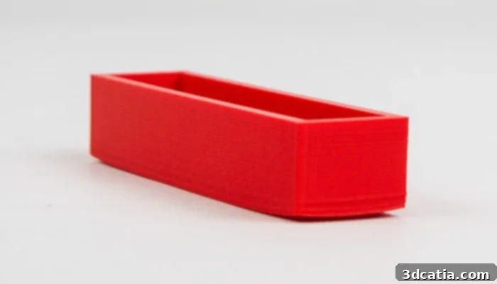
Warping, a common adhesion issue, can cause the part to lift and become detached.
One of the most frequently encountered adhesion problems is **warping**. This occurs when the corners or edges of your printed part curl upwards and sometimes completely detach from the build plate. Warping is particularly prevalent with larger prints or models made from materials prone to significant thermal contraction, such as ABS, nylon, and PEEK. The underlying cause is the plastic’s tendency to shrink as it cools. For example, ABS printed at 230°C can contract by nearly 1.5% when it returns to room temperature. This differential cooling creates stress that pulls the corners upwards. To combat warping, the use of a heated build plate is strongly recommended. A heated bed maintains the filament at or near its glass transition temperature, significantly reducing thermal stress and contraction. Always consult your filament packaging for the optimal build plate temperature. Additionally, reducing the printing speed, especially for the crucial first layer, allows the material more time to properly bond with the print surface before cooling. For more challenging materials, consider using an enclosure to maintain a stable ambient temperature, and slicer features like brims or rafts can further enhance initial layer adhesion and prevent lifting.
Conversely, you might face the problem of **excessive adhesion**, where the printed part sticks too well to the platform, making removal difficult and risking damage to both the print and the build plate. The primary rule here is patience: always allow the model to cool down completely before attempting removal. Many build plates release parts more easily once cooled. For particularly stubborn prints, placing the build plate (with the part still attached) into a freezer can help, as the differential contraction of the materials often aids release. If gentle cooling isn’t enough, a dedicated spatula or scraper can be used, but extreme care is vital to avoid scratching the build plate or damaging the model. Another technique involves immersing the plate and part in a hot water bath, but ensure the water temperature does not exceed the model’s glass transition temperature, as this could cause deformation. In your slicing software, review and deselect additional adhesion parameters like ‘Brim’ or ‘Raft’ if they are not strictly necessary, as these can contribute to over-adhesion and make removal more challenging for future prints.
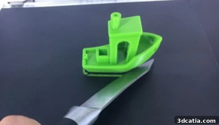
A spatula can be used to carefully remove a stubbornly adhered 3D print.
Combatting Elephant’s Foot
The “elephant’s foot” defect is characterized by the lower layers of a 3D print bulging outwards, creating a flared base reminiscent of an elephant’s foot. This cosmetic but often functionally disruptive problem arises when the initial layers haven’t cooled and solidified sufficiently before the weight of subsequent layers is applied, causing them to spread outwards under pressure. This can be exacerbated by a bed that is too hot or a nozzle that is too close to the build plate.
The first step to address elephant’s foot is to ensure your build plate is perfectly level. An uneven bed can cause varying distances between the nozzle and the plate, leading to inconsistent squishing and outward expansion on one side. Next, carefully adjust the temperature of your heated print bed. While a heated bed is essential for adhesion, if it’s set too high, the base layers will remain molten for too long. Reduce the bed temperature incrementally until you find a sweet spot where adhesion is maintained but the bottom layers cool enough to support the growing structure. Crucially, allow the lower layers to cool sufficiently but not too rapidly, as excessive cooling can induce warping. Consider optimizing your cooling system, perhaps by increasing the fan speed after the initial layers. Alternatively, if printing multiple parts, the printer takes longer to complete each layer, providing more time for the previous layers to cool and harden, which can naturally mitigate this defect. Some advanced slicer settings also allow for a ‘chamfer’ or ‘skirt’ at the base of the model, which can absorb some of the outward pressure, effectively hiding or reducing the appearance of elephant’s foot.
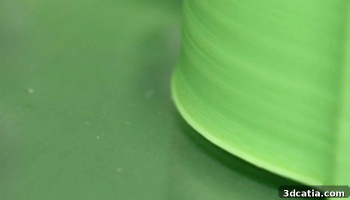
The first layer appears visibly swollen and wider than subsequent layers, indicating elephant’s foot.
Resolving Under-Extrusion Issues
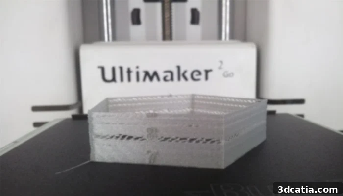
Under-extrusion is a common 3D printing problem where the printer’s nozzle fails to extrude the expected amount of material. This defect manifests as visible gaps between layers, weak layer adhesion, and thin, brittle prints that can easily crumble. Essentially, the volume of plastic exiting the nozzle is less than what the slicing software commands, leading to incomplete or sparse infill, and visible lines on external walls. Several factors can contribute to under-extrusion, ranging from incorrect software settings to physical obstructions within the printer’s filament path.
The first critical check involves verifying the filament diameter setting in your slicing software; it must accurately match the physical diameter of your filament (e.g., 1.75mm or 2.85mm). An incorrect setting will lead to the software commanding an inappropriate amount of material. If the diameter is correct but under-extrusion persists, adjust the extrusion multiplier (also known as ‘Flow Rate’) in your slicer. Increase this value in small increments, typically 1-5%, and print a test cube after each adjustment to find the optimal flow that ensures smooth, full layers without over-extrusion. Another frequent cause is a partially or completely clogged nozzle. Material residues, dust, or heat creep can block the tiny opening. Solutions include performing a ‘cold pull’ (atomic pull), using a nozzle cleaning needle, or replacing the nozzle entirely. Furthermore, check for any obstructions in the filament path upstream of the extruder, such as tangled filament on the spool, a kinked PTFE tube, or worn extruder gears that aren’t gripping the filament properly. Ensuring the filament can feed freely and that your extruder is applying consistent pressure is vital for preventing under-extrusion.
Correcting Over-Extrusion Problems
Over-extrusion is the inverse of under-extrusion, occurring when the 3D printer extrudes too much material. This excess plastic can negatively impact print quality, leading to bulging walls, distorted external dimensions, blobs, zits, and a generally messy appearance. Instead of smooth, consistent layers, you’ll see an abundance of material that can make parts rough to the touch and difficult to fit together if they are designed to be interlocking. Like under-extrusion, this problem primarily stems from miscalibrated settings or issues with material flow.
The solutions for over-extrusion largely mirror those for under-extrusion, but in the opposite direction. Begin by double-checking the filament diameter in your slicing software; if it’s set too small, the software will compensate by pushing more material than necessary. If the diameter setting is accurate, the next step is to reduce the extrusion multiplier (Flow Rate) in your slicer. Decrease this value incrementally, usually by 1-5% at a time, and print test pieces to observe the effect. The goal is to find a balance where layers are fully formed without any excess material oozing out. Additionally, ensure your printing temperature is not excessively high. A filament printed at a temperature significantly above its ideal range can become too fluid, causing it to flow out of the nozzle more freely than intended, contributing to over-extrusion even with correct flow settings. Calibrating your extruder’s E-steps can also precisely control the amount of filament pushed, offering a fundamental solution for both under and over-extrusion.
Eliminating Holes in 3D Printed Top Layers
Once a 3D print is completed, discovering unexpected holes or gaps in the top surface can be incredibly frustrating. This issue often makes prints look unfinished and compromises their structural integrity and aesthetics. These holes typically form when there isn’t enough material to properly bridge over the internal infill or hollow sections, or when manufacturing parameters are not correctly optimized. This problem is particularly common with models that have hollow interiors or intricate honeycomb infill patterns, as the top layers struggle to create a solid, continuous surface without adequate support from below.
The most direct solution is to increase the number of **top solid layers** in your slicing software. If your model’s interior is hollow or uses a sparse infill, a single or even a few top layers might not be enough to form a complete, solid roof; the plastic will likely sag or fall into the empty spaces. Aim for a sufficient number of top layers, generally 5 to 6 layers or a thickness of at least 1mm, to ensure a robust and smooth top surface. The surface quality visibly improves with each additional solid layer. Another effective solution is to increase the **infill density**. A higher infill density creates a more substantial internal support structure, reducing the distances the top layers need to bridge and providing a better foundation for them to rest upon. This makes it easier for the plastic to solidify into a smooth, continuous surface. Ensuring adequate infill overlap percentage (how much the infill overlaps with the perimeters) also helps eliminate gaps. Finally, ensure your printing temperature is appropriate; if the filament isn’t sufficiently molten, it may not spread and bond effectively to form solid top layers.
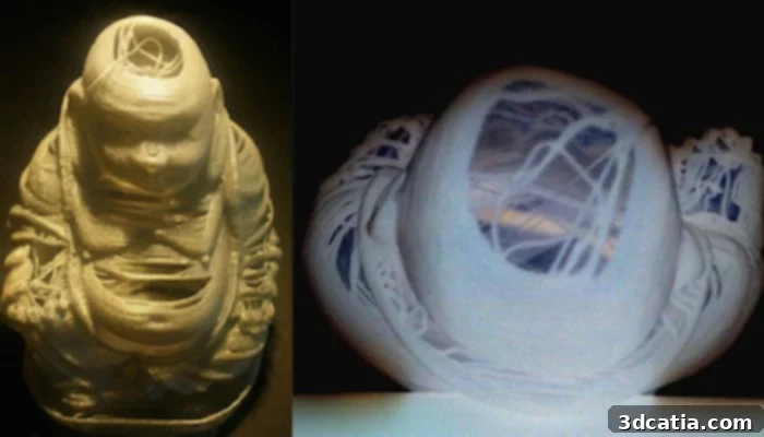
Several solutions exist to prevent unsightly holes from forming in the upper layers of 3D prints.
Troubleshooting Stringing (Oozing)
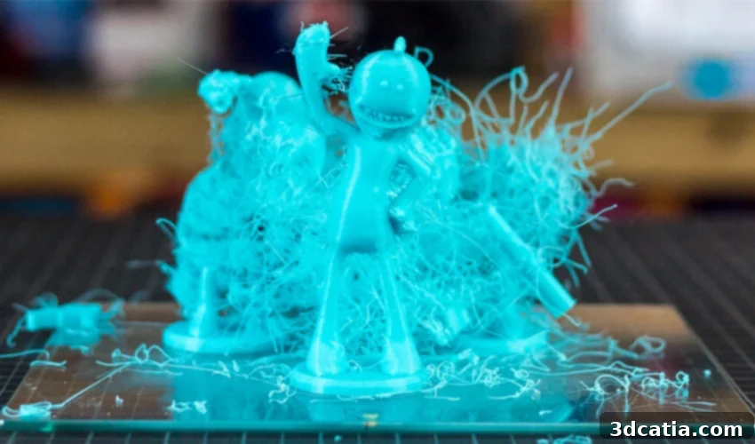
“Stringing,” also known as oozing or “hairiness,” is a common aesthetic defect characterized by thin threads of filament left behind between different sections of a 3D printed part. These unwanted strands occur when the printer’s nozzle moves from one point to another without extruding material, but molten plastic inadvertently oozes out. Ideally, the 3D printer should prevent this by retracting the filament slightly into the nozzle during non-printing travel moves. If these retraction parameters are not correctly configured, or if other conditions are unfavorable, these fine strings will appear, requiring post-processing cleanup and potentially degrading the overall finish of the print.
The primary solution to stringing lies in optimizing your **retraction settings**. Experiment with both the retraction distance and retraction speed in your slicing software. A good starting point for retraction speed is typically between 20 to 100 mm per second, depending on your printer’s direct drive or Bowden setup. Bowden systems generally require longer retraction distances due to the longer tube. Increase the retraction distance gradually until stringing is minimized. Another significant factor is the **extrusion temperature**. If the print temperature is too high, the plastic becomes excessively liquid, making it more prone to oozing even with retraction. Try lowering your print temperature in small increments (5-10°C) until stringing reduces, ensuring it doesn’t lead to under-extrusion or poor layer adhesion. Furthermore, ensure your filament is dry; wet filament can lead to steam bubbles that cause erratic extrusion and stringing. Utilizing a filament dryer can prevent this. Lastly, consider optimizing your **travel settings**: shortening travel distances where possible and increasing travel speed can reduce the time the nozzle spends moving without printing, thereby minimizing opportunities for oozing. Features like “Combing” in slicers, which keeps the nozzle within printed areas, can also help.
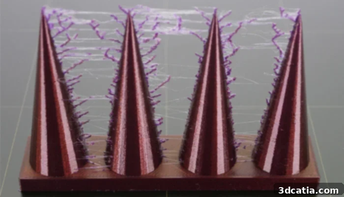
Unwanted threads appear between different sections of the 3D printed model.
Preventing Layer Separation (Delamination)
Layer separation, or delamination, is a critical structural failure where previously deposited layers of a 3D print fail to bond properly with subsequent layers, leading to visible cracks, gaps, or even complete detachment of sections of the print. This defect results in a weak, brittle part that can easily break along these separation lines, significantly compromising its mechanical strength and usability. The problem arises when the molten plastic from the nozzle doesn’t fuse effectively with the already deposited and partially cooled layer below it.
One of the most common causes of layer separation is an excessively high **layer height**. A general rule of thumb states that your layer height should not exceed 80% of your nozzle’s diameter. If the layer height is too great, the extruded plastic might not have enough surface area or sufficient pressure to properly “squish” and bond with the previous layer. Reducing the layer height provides more contact surface and promotes better adhesion. If your layer height is already optimized, the next crucial step is to **increase the printing temperature**. Hotter plastic is more molten and therefore more capable of fusing effectively with the layer beneath it. The ideal processing temperature for each filament is typically indicated on its packaging; adhere to these recommendations to ensure optimal layer adhesion. Rapid cooling due to drafts or excessive fan speed can also lead to delamination, especially for materials like ABS. Consider using a printer enclosure to maintain a stable ambient temperature, and reduce or turn off the cooling fan for the initial layers, particularly for materials sensitive to rapid cooling. Ensuring a proper first layer “squish” by fine-tuning your Z-offset also contributes significantly to overall part strength and layer adhesion.
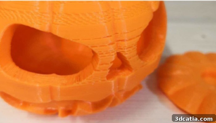
Visible separations can occur between some layers, leading to structural weakness.
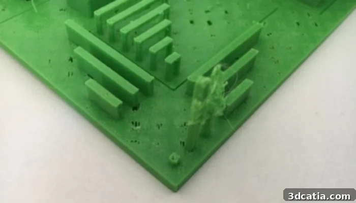
Troubleshooting Unprinted Fine Details
In the realm of 3D printing, especially as it’s increasingly utilized for intricate designs, achieving fine and precise details is paramount. However, FDM technology inherently has limitations when it comes to printing extremely small or thin features. If you attempt to print areas that are finer or thinner than your nozzle’s diameter, or below the mechanical limits of the printer, you will inevitably encounter problems, ranging from missing features to poorly defined elements.
The most straightforward solution for improving fine detail resolution is to **use a smaller diameter nozzle**, if your printer supports it. A 0.2mm or 0.25mm nozzle, for instance, can produce significantly finer details than a standard 0.4mm nozzle. However, printing with smaller nozzles often requires slower print speeds and carefully calibrated flow settings to prevent clogging. Your slicing software can also offer specialized settings or profiles designed to enhance fine feature printing, sometimes allowing for features thinner than the nozzle diameter by utilizing ‘print thin walls’ or ‘vase mode’ functions. The quality of your filament can also play a role; high-quality filaments with consistent diameter and good flow characteristics tend to perform better with intricate geometries. If all these adjustments are insufficient or not feasible, the most reliable solution might be to **redesign the part** with thicker features that are within the FDM printer’s capabilities. Modern slicing software, such as Cura, Z-Suite, or Simplify3D, often includes features that can analyze your 3D model and warn you if it contains components that are too thin to be reliably printed, helping you to make design adjustments proactively.
As this guide illustrates, numerous challenges can arise during FDM 3D printing, each requiring a nuanced approach to diagnosis and resolution. While finding the exact cause of a print defect may sometimes seem daunting, troubleshooting is an inherent part of the learning curve in 3D printing. The journey from a raw design to a perfectly finished print often involves iteration and experimentation with various machine parameters and slicer settings. Don’t be discouraged by initial failures; instead, view them as valuable learning opportunities. Consistency, practice, and a systematic approach to problem-solving are key to mastering the art of FDM 3D printing. Furthermore, the 3D printing community is a vast resource. Many manufacturers are actively developing advanced 3D software capable of identifying and even automatically correcting common printing defects. We strongly encourage you to test different parameters on your machine to understand what works best for specific materials and geometries. If you encounter a persistent 3D printing problem, don’t hesitate to share your experiences and seek advice in the comments section below or engage with the knowledgeable members of the 3Dnatives forum. Your insights and questions contribute to the collective knowledge of the community! Let us know your thoughts and challenges on our Facebook and Twitter pages!