Software
Topology Optimization vs. Generative Design: Which Modeling Tool Should You Choose?
There is a constant race for even faster production, parts meeting higher demands and to surpass our current accomplishments. To achieve this, the products we manufacture have to be optimized in one way or another, so that they perform even…
- 3 min read
- Software
- Six more stories
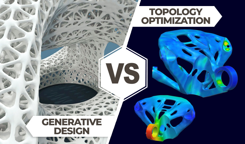
There is a constant race for even faster production, parts meeting higher demands and to surpass our current accomplishments. To achieve this, the products we manufacture have to be optimized in one way or another, so that they perform even better. Often, this means reducing the weight of parts while striving for greater strength and performance. And this “less is more” equation starts right at the design stage! While designers strive to work designs in this direction, new technologies such as artificial intelligence and machine learning bring new possibilities, as is the case with topology optimization and generative design.
Topology optimization and generative design are two approaches which, with the help of computer-aided calculations, optimize designs so that they are more efficient, saving on costs and resources during production, to name but a few incentives.Although the two methods pursue similar objectives, they should not be equated or confused. We took a closer look at what is meant by topology optimization and generative design, the advantages, challenges, concrete fields of application and examples, and explain their usefulness in combination with 3D printing.
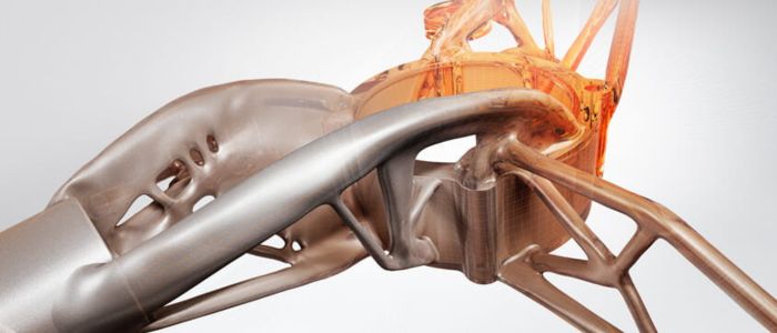
Photo Credits: Mensch und Maschine
Get the Best Design Faster With Topology Optimization and Generative Design
Topology optimization is not a new method in itself, and has been used since the early 1990s to optimize 3D models in such a way as to retain basic functions while saving materials when the part is not required to carry loads. Topology optimization always begins with a human design, which must be adapted so that performance is not reduced despite the savings made. To achieve this, however, it is necessary to define certain framework conditions, such as taking account of the forces at work and defining protected zones. Computer algorithms then create a mesh model whose structural integrity must be verified during finite element analysis (FEA). The result must then be checked and, if necessary, adapted by a CAD engineer.
More from the desk
Six other notes from the rest of the bench.
 MaterialsTop 5 Videos: Mimaki & Open BionicsThis week’s Top 5 Videos showcases some of the most unbelievable 3D printing updates we’ve seen in recent times. These include incredibly detailed full-color 3D prints by Mimaki, amazing 3D printed prosthetics by Open Bionics, and Qlone’s 3D scanning app…
 NewsOWA Speaker: The 3D Printed Speaker based on a Circular EconomyOWA 3D have just launched their Kickstarter campaign for their DOT project which they also presented at CES 2018 in Las Vegas. This collaboration between 5 French companies led to the creation of the first customisable Bluetooth 3D printed speaker,…
 NewsEOS Has Developed a Solution for Support-Free Metal 3D PrintingToday, metal 3D printing is primarily aimed at professionals, opening up new avenues for them in various industries. Indeed, a study by Grand View Research while the market value in 2022 was already $4.06B, this value is already forecast to…
 PrintersBCN3D Has Launched its New 3D Printer Cloud Management TechnologyEarlier this year, leading FDM printer manufacturer BCN3D acquired 3D printing cloud software management platform AstroPrint. Now, building on that acquired cloud technology, the Barcelona-based company is launching a new cloud platform, that will allow the centralization of remo
 MaterialsProdways’ New Breakthrough Resin for the Dental IndustryThough one of Europe’s leading manufacturers of 3D printers, Prodways offers solutions across the entire 3D printing value chain and for several industries. Earlier this month, the company launched its first automated 3D printing modular system for the dental industry,…
 GuidesThe Top 3D Printed Pavilions Around the WorldA pavilion is defined by the the Merriam-Webster dictionary as an “a usually open sometimes ornamental structure in a garden, park, or place of recreation that is used for entertainment or shelter.”. In recent years, there has been an increasing…