
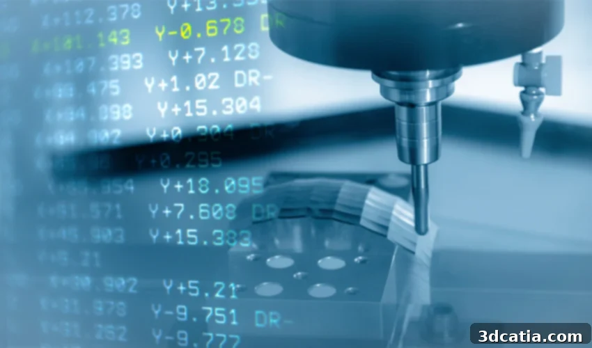
Mastering G-Code: The Universal Language of 3D Printers for Optimal Additive Manufacturing
In the exciting world of additive manufacturing, creating a physical object from a digital design is a process that extends far beyond merely powering on a machine and pressing a button. It involves a meticulously choreographed sequence of steps, from the initial design and modeling of a part to its complex final post-processing, with numerous critical stages in between. Among these vital prerequisites for successful 3D printing is the crucial step of preparing your model using specialized cutting software, commonly known as slicers. These powerful programs serve as the essential bridge between your digital design file, typically an STL, and the physical actions of your 3D printer. They convert the geometric data into a precise set of instructions, a control file composed of what is known as G-Code. This programming language is the bedrock upon which all 3D prints are built, allowing the machine to understand precisely what commands it must execute to manufacture the final part with accuracy and consistency. But what exactly is this digital language, and how profoundly important is it in the entire additive manufacturing workflow?
Understanding G-Code: The Digital Blueprint for 3D Printing
At its core, G-Code is a numerical control programming language, initially developed for computer numerical control (CNC) machines, and later adapted for the unique requirements of 3D printers. It consists of a series of sequential commands, primarily designated as G-commands (for geometric or preparatory functions) and M-commands (for miscellaneous or machine-specific functions), each assigned a specific motion, action, or machine control operation. The intricate combination of these commands provides the 3D printer with a detailed blueprint, enabling it to interpret the precise pattern it must follow to create the final part layer by layer. As we’ve highlighted, this language is not typically written manually by the user, but rather automatically generated by sophisticated slicer software when it converts a 3D model’s design into an STL file ready for printing.
While G-Code is used across various additive manufacturing technologies, our discussion here will primarily focus on FDM (Fused Deposition Modeling) 3D printers. This means we will frequently refer to components and concepts such as the extruder, the heated print bed (or print tray), and thermoplastic filaments, as these elements are directly controlled by specific G-Code commands. The different types of commands that an FDM 3D printer will interpret fall broadly into categories including movement commands, extrusion commands, heating commands, and detection commands. These are executed in a precise sequence, ensuring that each layer is laid down correctly and that the printer operates within specified parameters. This sequential interpretation forms the fundamental basis for understanding the critical importance of this language in bringing digital designs to life. To truly grasp its power, let’s now delve into the numerical and alphanumeric composition of a G-Code line to be able to read and interpret the individual commands.
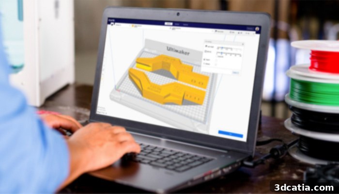
The G-Code language is automatically generated by the slicer, serving as the machine’s instructions (photo credits: Ultimaker Cura)
Deconstructing G-Code: What are the Components?
To begin dissecting the structure of G-Code, it’s essential to understand the nuanced distinction between G-Codes and M-Codes. Both are integral commands included within the G-Code file and collectively instruct the 3D printer on how and where to extrude material, how fast to move, and how to manage its various systems. The primary difference lies in their universality and function. G-Codes typically refer to commands that dictate motion, tool paths, or general preparatory actions (e.g., rapid moves, linear moves, dwelling), and are generally understood across most CNC and 3D printing platforms. M-Codes, on the other hand, represent miscellaneous functions and are often specific to individual printer lines, firmware versions, or machine configurations. They control specific machine features such as turning fans on/off, managing heaters, or handling specific tool changes. Therefore, while a G-code like G1 (linear move) is almost universally interpreted, an M-code might vary in its exact implementation or even existence across different printer manufacturers.
As we can discern from looking at an example G-Code snippet, the language is comprised of several critical parameters, each represented by an alphanumeric value. Understanding these basic elements is key to deciphering the commands. Let’s explore the most fundamental alphanumeric values you’ll encounter:
- X / Y / Z: These letters refer to the three fundamental axes of the 3D printer, which establish the Cartesian coordinates in the build volume. Any positive value for X (e.g., X10) typically moves the printhead to the right from the printer’s home position. A positive value for Y (e.g., Y20) moves the printhead backward along the print bed, away from the front of the machine. A positive value for Z (e.g., Z0.2) moves the printhead upwards, incrementing the layer height. These three axes are pivotal for precise positioning and defining every point where material is deposited or the nozzle travels.
- F (Feed Rate): This parameter dictates the speed at which the nozzle or printhead moves. It is typically indicated in millimeters per minute (mm/minute). A higher F value means faster movement, which can impact print speed but also print quality and accuracy, especially during intricate operations or when bridging. Proper feed rate is crucial for both printing and non-printing travel moves.
- E (Extrusion): The E parameter specifically refers to the length of filament to be extruded or retracted, also indicated in millimeters (mm). Positive E values (e.g., E1.5) command the extruder motor to push filament out of the nozzle, depositing material. Negative E values (e.g., E-0.5) command retraction, pulling filament back to relieve pressure and prevent oozing during travel moves. The precise control of extrusion is fundamental for preventing issues like underextrusion or overextrusion, which directly affect part strength and aesthetics.
- S (Temperature): While not explicitly mentioned in the original list for X/Y/Z/F/E, the ‘S’ parameter is commonly used with M-Codes to specify target temperatures, for instance, for the extruder or the heated bed. It’s usually indicated in degrees Celsius.
- T (Tool Index): For 3D printers equipped with multiple extruders (dual extrusion or multi-material systems), the ‘T’ parameter is used to specify which extruder (e.g., T0, T1) a subsequent command should apply to.
- Comments (`;`): Sometimes, you’ll find text following the symbol “;” (semicolon) within a G-Code file. These are comments and serve to provide human-readable information or annotations about a specific command or section of the code. Importantly, these comments are ignored by the 3D printer’s firmware and are not part of the executable code. They are invaluable for understanding the context of the generated G-Code or for manual debugging.
Having grasped the fundamental building blocks and how G-Codes can be read, let’s now explore some of the most common and essential G-Code and M-Code commands crucial for the manufacturing process of a 3D printed part.
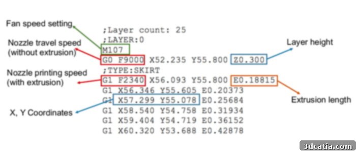
Examples of fundamental G-Code commands for 3D printing
Essential G-Code Commands for 3D Printing Operations
Understanding these common commands provides valuable insight into the printer’s operations and can be crucial for troubleshooting or fine-tuning prints:
- G0 (Rapid Linear Movement): This command instructs the 3D printer to perform a rapid linear motion from its current position to the specified coordinates (X, Y, Z) without extruding any material. It prioritizes speed over precision, making it ideal for travel moves where the nozzle needs to quickly reposition itself across the print bed or between print features without depositing filament. For example,
G0 X50 Y100 F6000would tell the printer to move to X=50mm, Y=100mm at a high feed rate of 6000 mm/min, without extruding. - G1 (Controlled Linear Movement with Extrusion): The G1 command is arguably the most frequently used G-Code, often comprising over 95% of a typical print file. It instructs the 3D printer to perform a controlled linear motion while actively depositing material (extruding) to the specified location at the given coordinates (X, Y, Z, and E for extrusion). The movement is executed at a defined feed rate (F). So, when you read the code
G1 X10 Y20 E0.5 F1200, you are instructing the printer to move linearly to the X=10mm, Y=20mm position on the print tray, extruding 0.5mm of filament, at a controlled speed of 1200 mm/min. This command is the workhorse for creating all printed features, from perimeters to infill. - G28 (Auto Home): This command is vital for initiating any 3D printing process. It instructs the machine to execute its start sequence, which involves moving the printhead and/or print bed to their respective home positions by making contact with mechanical or optical endstops. This process resets the printer’s internal coordinate system (X, Y, and Z axes) to their known zero points, ensuring accurate positioning for the subsequent print. If no specific axis is designated (e.g.,
G28), the machine will automatically home all three axes. However, you can specify individual axes likeG28 XorG28 Zto home only that particular axis, which is useful for moving an axis out of the way or resetting its position after a manual adjustment. - G29 (Auto Bed Leveling): For printers equipped with bed leveling probes (like BLTouch or inductive sensors), the G29 command initiates an automatic bed leveling sequence. The printer will move its nozzle or probe across various points on the print bed, measuring the distance to the bed at each point. This creates a mesh of the bed’s surface, allowing the firmware to compensate for any unevenness during printing, significantly improving first-layer adhesion and overall print quality, especially on larger or slightly warped beds.
- G92 (Set Position): This command is used to instruct the printer to set the current position of its axes to new, user-defined values. This can be incredibly useful if you want to change or offset the apparent location of one or more axes without physically moving them. For instance,
G92 E0is a very common command used at the beginning of print layers or before major extrusion commands to reset the extruder’s position to zero. This ensures that subsequent extrusion commands (E values) are relative to this new zero point, preventing cumulative errors in filament length. It is also often used for fine-tuning specific starting points or calibration routines. - M104 (Set Extruder Temperature, Non-Blocking): This command is used to heat a specific extruder to a desired temperature. You must indicate which extruder (e.g., T0 for the primary extruder in a dual extrusion setup, T1 for the secondary) and the target temperature using the ‘S’ parameter. For instance, the command
M104 S200 T0will order the machine to begin heating extruder T0 to a temperature of 200 degrees Celsius. Crucially, M104 is a non-blocking command, meaning the printer will initiate the heating process and then immediately proceed to the next G-Code command without waiting for the target temperature to be reached. This can speed up print start-up sequences if other actions can occur simultaneously. - M109 (Set Extruder Temperature, Blocking): Similar to M104, this command also sets the extruder temperature. However, the key difference is that M109 is a blocking command. The printer will heat the specified extruder to the target temperature (e.g.,
M109 S210 T0for extruder T0 to 210°C) and then pause, waiting until that temperature is fully reached and stabilized before continuing with any subsequent commands in the G-Code file. This is often used in the start G-Code to ensure the nozzle is at the correct temperature for extrusion before the print begins, preventing issues like cold extrusion or clogs. - M140 (Set Bed Temperature, Non-Blocking): Analogous to M104, the M140 command initiates the heating of the print bed to a specified temperature. For example,
M140 S60would tell the printer to start heating the bed to 60 degrees Celsius. Like M104, this command is non-blocking, allowing the printer to continue processing other commands while the bed warms up. The ‘T’ parameter for extruder index is omitted here as it applies specifically to the print bed. - M190 (Set Bed Temperature, Blocking): This command, similar to M109, sets the print bed temperature but is a blocking command. The printer will heat the bed to the specified temperature (e.g.,
M190 S60) and then wait until the bed has reached and stabilized at 60 degrees Celsius before moving on to the next instruction. This ensures proper bed adhesion and reduces warping by starting the print only when optimal conditions are met. - M82 / M83 (Set Extruder to Absolute / Relative Mode): These commands are crucial for how the extruder interprets subsequent ‘E’ values.
M82sets the extruder to absolute positioning mode, meaning all ‘E’ values are interpreted as the total length of filament extruded since the start of the print or the lastG92 E0command.M83sets the extruder to relative positioning mode, where ‘E’ values are interpreted as the amount of filament to extrude *from the current position*. Slicers typically generate G-Code in absolute extrusion mode (M82) after aG92 E0command, as it helps prevent cumulative errors. - M106 / M107 (Fan Control): These commands control the printer’s cooling fans.
M106 S[speed]turns the part cooling fan on at a specified speed (0-255 or 0-100% depending on firmware, e.g.,M106 S128for 50% speed).M107turns all fans off. Proper fan control is essential for cooling filament layers rapidly, which is critical for bridging, overhangs, and preventing heat creep. - M117 (Display Message): A simple yet effective command,
M117 [message]allows the printer to display a custom message on its LCD screen. This is often used in start or end G-Code to provide status updates, such as “Printing…” or “Print complete!” to the user. - M18 / M84 (Disable Stepper Motors): These commands disable the stepper motors that control the printer’s axes (X, Y, Z, and E).
M18orM84(often interchangeable depending on firmware) can be followed by specific axes (e.g.,M84 X Y) or disable all motors if no axes are specified. Disabling motors allows manual movement of the printhead and bed, which is useful for maintenance, cleaning, or precise initial positioning. It’s often used at the very end of a print to allow the user to remove the part easily.
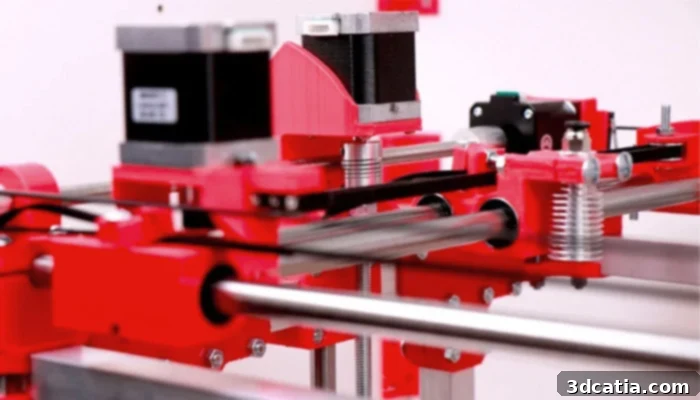
FDM 3D printers rely on X, Y, Z axes to position the printhead accurately within the printing coordinates
The Role of Slicers and Advanced G-Code Customization
The complexity of G-Code, with its hundreds of distinct commands and parameters, underscores the indispensable role of slicer software. Tools like Ultimaker Cura, PrusaSlicer, and Simplify3D act as sophisticated interpreters. They take your intricate 3D model, virtually “slice” it into thousands of horizontal layers, and then generate the precise G-Code instructions for each layer. These instructions dictate everything from the toolpath the nozzle follows, the exact amount of filament to extrude, the speed of movement, fan speeds, and temperature settings, all based on the user-defined print settings (layer height, infill density, print speed, temperatures, retraction settings, etc.). The slicer effectively translates your high-level print preferences into the granular, machine-specific language your 3D printer understands.
While the automatic generation of G-Code simplifies the printing process for most users, understanding its underlying structure offers significant advantages, especially for advanced users and troubleshooting. Knowing what each command means can empower you to diagnose print failures, fine-tune specific print parameters mid-print, or create custom start and end G-Code sequences. For instance, if you’re experiencing stringing, understanding retraction commands (E values) can guide your adjustments. If layers are delaminating, checking temperature commands (M104, M109, M140, M190) might reveal insufficient heat. Manual editing can introduce pauses at specific layers for color changes or to embed components, or even modify speeds for critical sections of a print. This deeper knowledge transforms a passive user into an active participant in the machine’s operation.
Final Recommendations and the Power of Knowledge
The extensive list of G-Codes and M-Codes available in modern 3D printing firmware is truly vast, often exceeding a thousand different commands. These commands allow for an astonishing level of control, dictating every minute action and state of the 3D printer at any given moment. This inherent complexity is precisely why the language is almost always automatically generated by slicer software prior to the actual manufacturing process, abstracting away the intricate details from the average user.
Nevertheless, gaining a foundational understanding of these core codes can be incredibly useful and immensely interesting for any enthusiast or professional looking to deepen their expertise in additive manufacturing. It provides invaluable insight into how your printer operates and how slicer settings translate into physical actions. However, a strong word of caution is necessary: manually writing or extensively editing G-Code is a task best reserved for experienced users. Incorrect modifications can lead to unexpected behavior, failed prints, or even potential damage to your 3D printer’s components if critical parameters like motor speeds or temperature limits are mishandled. Unless you possess a very clear understanding of what you intend to edit and the potential repercussions, we strongly advise against users generating the part coding themselves or making arbitrary changes to automatically generated G-Code files.
Despite the warnings, we wholeheartedly encourage you to continue exploring and learning about the inner workings of these advanced manufacturing solutions. Delving into the different commands available, understanding their syntax, and appreciating the intricate system used in a technology of this caliber will undoubtedly enhance your 3D printing journey. It opens up avenues for advanced troubleshooting, customization, and ultimately, greater control over your additive manufacturing projects.
What are your thoughts on the significance and use of G-Codes in 3D Printing? Share your insights in a comment below or join the conversation on our Facebook and Twitter pages. Don’t forget to sign up for our free weekly newsletter, delivering all the latest news, innovations, and insights in the world of 3D printing straight to your inbox!